|
 |
|||||
|
|
background
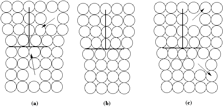
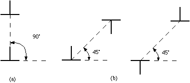
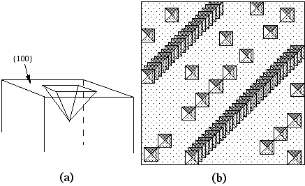
The atomic displacements near a dislocation are a source of internal stress. In the diagram of the positive edge dislocation shown in Fig. 2 (a), it is clear that the upper half of the crystal, where the extra half plane has been inserted, is under compression and the bottom half of the crystal is under tension. The stress fields that result from the compressive and tensile forces around different dislocations interact with one another. If the dislocations are free to move, we expect them to take up positions that minimize their elastic energy. There are two types of dislocation motion, glide and climb. When a dislocation moves by glide, as illustrated in Fig. 2, it remains in the same slip plane. This process, called conservative motion, can occur at relatively low temperatures. Climb, on the other hand, is a nonconservative motion that involves the creation and migration of point defects. Thus, it is temperature activated and occurs only at higher temperatures. This process is illustrated in Fig. 3. Figure 2. Dislocation glide. An edge dislocation moves to the right and eventually exits the crystal. Figure 3. Dislocation climb. In (b) the edge dislocation is centered. By adsorbing vacancies it can climb in the positive direction, as shown in (a). By emitting vacancies it can climb in the negative direction, as shown in (c). Equilibrium configurations of dislocations of the same and opposite signs have been determined theoretically and the results are summarized in Fig. 4. In arriving at these configurations, it was assumed that only glide was possible. A somewhat different result occurs if climb is active. For example, consider the attractive interaction of two edge dislocations of opposite sign (if the edge dislocation shown in Fig. 2 is a positive dislocation, then a negative edge dislocation is one in which the extra half plane is inserted from below). If these two dislocations are permitted to climb towards each other, they annihilate. Figure 4. The equilibrium configuration of edge dislocations free to glide (a) of the same sign, (b) of opposite sign. We will determine the positions at which dislocations intersect the cleaved surface of a crystal by examining etch pits. An example of such pits is shown in Fig. 5. During dissolution, atoms from near the dislocation are removed at different rate from those far from the dislocation. This process, which results in the formation of an etch pit, occurs because of the bond strain near the dislocation (atoms in the strained positions are more easily removed) and the impurities that concentrate near the dislocation. In practice, producing visible etch pits can be difficult since it is important that the removal rates from the ideal and defective areas occur in the proper ratio. Figure 5. Dislocation etch pits. (a) a three dimensional view of a pit with square pyramidal facets. (b) Projection showing schematic distribution on the surface. In our experiment we will use single crystals of rock salt (NaCl). Not only is the observation of etch pits simplified in this material, but it is also easily cleaved and deformed. |
||||
|
|
|||||


